
Quick Links
- www.4004.com for lots of info on Intel 4004 processor.
- Busicom 141-PF ROM images disassembled, commented and documented
- Busicom 141-PF story on vintage calculator site
- Busicom 141-PF page on vintage calculator site
Credits
I like to thank following for extracting rare ROM images and making them available for public:
- www.4004.com team
- 4004 design team
- Computer History Museum
- Tim McNerney for printer emulation code.
- Busicom 141-PF picture by Swtpc6800 Michael Holley .
- 4004 picture By Thomas Nguyen - Own work, CC BY-SA 4.0
Pictures I used from others have credits/links close to the images as they are used.
Intro
Let me first let it out. I became one of the few people who programmed world’s first microprocessor 4004 and also got to experience the world’s first calculator w/ that processor. Now that’s out, let’s dive into how I did it so you can do too.

Thankfully we can still find intel 4004 processors on eBay. However we need the rest of the hardware to get it working. This is where RetroShield for Arduino Mega project comes in. RetroShield enables us to connect the microprocessor to Arduino and then emulate the rest of the hardware in software. Please find more details in this page.
Agenda below is we learn a bit about the calculator (printer and keyboard), how 4004 works, and how everything is connected.
I’ll add notes for Arduino side of things in this format.
Busicom 141-PF
World’s first microprocessor was designed by Intel (project led by Federico Faggin) for this special calculator by Busicom. Please visit the links I put above. I will say I’m glad they worked on this and opened a new chapter in history.

Busicom calculator was built using Intel MCS-4 family which is a collection of CPU, ROM, RAM, I/O chips that work literally collectively to execute code. It is collective because some of the instruction decoding is also done by the peripheral chips (as opposed to evertyhing done in CPU as we do now):
- i4004 CPU
- i4001 ROM (5 chips, total 1.25KB. 5th ROM optional for square root function. 4 I/O pins per chip.)
- i4002 RAM (2 chips, total 640 B. 4 Output pins per chip)
- i4003 Shift-register (3 chips, for printer & keyboard hardware)
You can study schematics at this link. Also check out the documented ROM image at 4004.com.
Arduino needs to emulate ROM, RAM, level shifters in addition to the keyboard and display functions.


Calculator hardware is controlled using GPIO’s on all the chips. Let me do a copy/paste from the documented assembly listing to give you an idea of what we need to figure out on Arduino side.
;The port bits of ROMs, RAMs and TEST pin of CPU are used for:
;
;TEST:	printer drum sector signal
;
;ROM0:	shifter output
;	bit0 = keyboard matrix column shifter clock (for a i4003 shifter)
;	bit1 = shifter data (shared for printer and keyboard matrix shifter)
;	bit2 = printer shifter clock (for two cascaded i4003 shifter)
;	bit3 = not used
;
;ROM1:	keyboard matrix rows input
;
;ROM2:	bit0 = printer drum index signal input
;	bit1 = not used
;	bit2 = not used
;	bit3 = printer paper advancing button input
;
;ROM3:	not used
;
;ROM4:	not used
;
;RAM0:	printer control outputs
;	bit0 = printing color (0=black, 1=red)
;	bit1 = fire print hammers
;	bit2 = not used
;	bit3 = advance the printer paper
;
;RAM1:	status light outputs
;	bit0 = memory lamp
;	bit1 = overflow lamp
;	bit2 = minus sign lamp
;	bit3 = not used
Couple of higlights:
- ROM0 GPIO’s are used to shift into the i4003 shift registers.
- One Shift register outputs are used for keyboard scanning
- Two shifter register outputs are used for printer hammer control.
- CPU constantly synchronizes w/ the spinning printer and fires hammers at the right time as needed.
Printer
Printer is a continously spinning drum filled w/ rings of digits and symbols. A set of hammers are lined up and ready to fire as needed. As the drum spins, different digits/symbols will line up under the hammers. We basically wait for the right digits to line up and then fire the hammers to form what we want to print on a line. Hence it may take full rotation of the drum to print what we want. Once we print the line, we hit the paper advance signal to move the paper up a bit.
Because the drum is spinning all the time, CPU needs to synchronize with it so it knows when each symbol arrives under the hammers. This is done by two signals:
- TEST input on CPU - asserted at each symbol time. happens very fast.
- ROM2.bit0 input - asserted as the index symbol (i.e. beginning symbol). This is used to make sure synchronization is correct.
With these, cpu synchronizes its internal tracker w/ the actual printer position and knows which symbol will arrive under which hammer.

Imagine the blue table below was wrapped around to make a cylinder. That’s the drum on 141-PF. Sector 0 is the beginning row and asserts the ROM2.bit0 input. As the drum rotates about 27.7 degrees and aligns w/ the hammers, TEST input to CPU gets asserted.
Columns 1 thru 15 have all the digits plus the dot symbol. Column 16 is empty. Column 17 and 18 has various symbols for operations. You will see an example output later on.

To print the result of SQRT(2), the code needs to go thru the following stages. Assume the printer was at sector 0 when we started printing the result:

- We have 0’s at the first row, so we can only fire the hammer at the 0 at the end.
- Then fire hammers for 1’s.
- Then fire hammers for 2’s. then for 3’s. etc.
- we do this while the printer is spinning constantly (not that we are advancing the printer ourselves).
- As drum rotates, the results starts to appear.
- Once done we advance paper.
We don’t always get lucky to start at sector 0. The ROM code will start printing at whatever the drum position was at so don’t need to wait for it to go back to sector 0.
Arduino needs to emulate the spinning drum with respect to teh CPU cycles. There is a tight relationship between the two. Printer can not spin too fast or too slow. Luckily, Arduino controls 4004 so we can emulate printer in cpu cycle units.
I used Tim McNerney printer emulation code. Arduino needed to keep track of shifter outputs. When the hammers were fired, I called Tim’s subroutines which keep track of which digits are fired and prints a complete line when paper advance signal is triggered.
Keyboard
Keyboard is easier because one shifter output (10 bits) is used to scan the buttons which feed into a 4bit input on ROM1. There is a mix of matrix scan for digits and buttons but also a few rotary switches for calculation mode (truncate, float, round) and number of significant digits.
Bill Kotaska’s replica schematic shows the matrix setup:
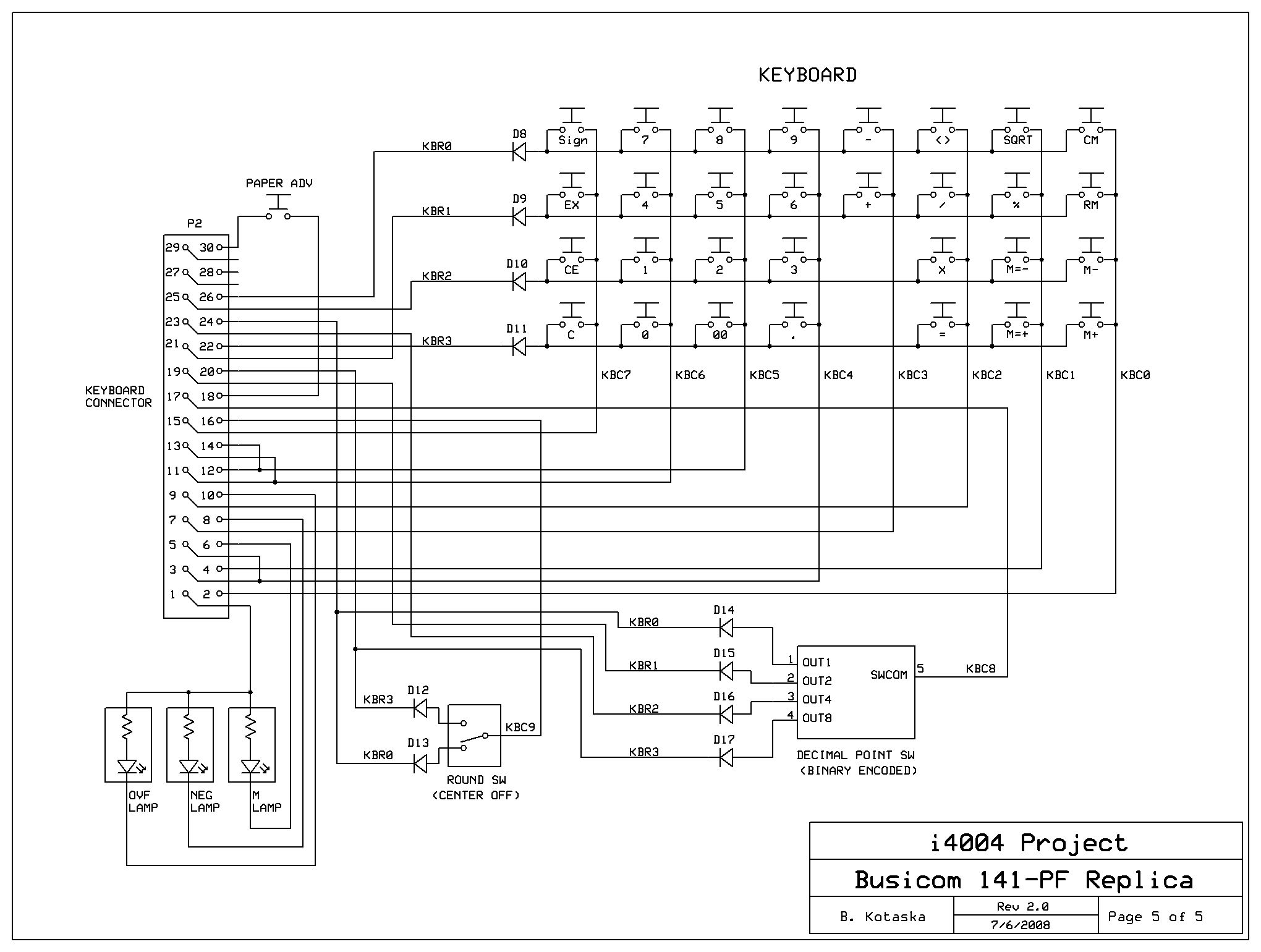
Since we don’t have a physical keyboard and rotary switches, Arduino needs to translate serial characters into this keyboard input.
The mapping in Arduino is done this way:
'X', 'V', 'Z', 'A',    // CM  RM  M-  M+
'S', '%', 'L', 'P',    // SQ  %   M=- M=+
'[', '/', '*', '=',    // DIA /   *   =
'-', '+', ']', 'O',    // -   +   D2  000
'9', '6', '3', '.',    // 9   6   3   .
'8', '5', '2', 'I',    // 8   5   2   00
'7', '4', '1', '0',    // 7   4   1   0
'Q', 'E', '`', 'C'     // SI  EX  CE  C

Use f/F to dec/increase digits after decimal point
Use R to select FLoat/TRuncate/ROund
? - print this help again.
Arduino maintains the state of these buttons and switches internally as they would in a physical world. What I mean by physical world is if a digit is pressed briefly, Arduino will assert the appropriate GPIO pins for X number of CPU cycles which correspond to how long the user would have pressed that button.
When there is a serial char input, Arduino will
- first check if it is a special key like f/F/R. if so it will update the rotary switch internally.
- if a physical button on the keypad is pressed, Arduino will emulate button press on GPIO pins for a set duration. It emulates button down and button up.
- if there are multiple chars received, it will emulate button presses with delays between each character.
4004
There are good books to read on 4004. I will summarize here:
- it’s a 4-bit processor so everything happens in nibbles.
- Address bus is 12bit long (it needs to push 4bit three times)
- Data bus is 4bits but instructions are 8bits (4bit instruction + 4bit data so each instruction is read in two cpu cycles.
- For absolute address jump instructions, multiple 4bits must be read from ROM.
- CMROM and CMRAM[3..0] are similar to chip-selects on modern processors.
- SYNC output indicates the last cycle of cpu instruction cycle. This signal helps all peripherals synchronize on bus transaction (we’ll talk shortly).
- TEST is an input which can be tested by instructions.
- CLOCK PHASE 1/2 - two phase clock input. Driven by Arduino.
- RESET - must be asserted to clear all internal registers.

One thing to note is 4004 is reverse voltage, meaning 1 means low voltage and 0 means high voltage. It is easy to do this translation in Arduino because it is code. To use or not to use
~. For example, SYNC input is captured as:
#define STATE_SYNC ( (~PINA) & 0x20)

As we said 4004 has 4 bit databus so it takes multiple clock cycles for each instruction cycle - 8 cycles to be exact.
- first 3 cycles are for pushing the address bus out
- then 2 cycles to read in the instruction byte (OPR + OPA)
- then 3 cycles to execute it.
- could be internal-only instruction (i.e. NOP, XCH, FIM)
- could be I/O setup instruction (SRC, DCL)
- could be I/O transfer instruction (accum <-> RAM or I/O)
- SYNC is asserted in last cycle.
This means Arduino needs to synchronize first so it can emulate hardware. The reset code will reset the processor and keep clocking until it sees SYNC signal.
I/O peripherals monitor M1 and M2 cycles so they can react during X1/X2/X3 accordingly.
Figuring out how peripherals worked during X1/X2/X3 cycle was the most challenging part of the bring-up. Thanks to Tim McNerney I figured it out and have a clear picture now.
Instruction Set
Summary instruction set from documented assembly listing. You can see why CPU needs to fetch 8 bits in two cycles:
;----------------------------------------------------------------------------------------------------------------------------------
;4.1	i4004 instruction set summary
;
;Opcode   2nd byte 		Mnemonic CY	description
;----------------------------------------------------------------------------------------------------------------------------------
;00000000		NOP	 -	No operation
;0001CCCC AAAAAAAA	JCN	 -	Jump conditional
;0010RRR0 DDDDDDDD	FIM      -	Fetch indirect from ROM into register pair
;0010RRR1		SRC	 -	Send Register Control
;0011RRR0		FIN	 -	Fetch indirect from ROM (register pair = indirect from location R0R1 of the same page)
;0011RRR1		JIN	 -	Jump indirect (8 bit of program counter = register pair)
;0100AAAA AAAAAAAA	JUN	 -	Jump unconditional
;0101AAAA AAAAAAAA	JMS	 -	Jump to subroutine
;0110RRRR		INC	 -	Increment register
;0111RRRR AAAAAAAA	ISZ	 -	Increment register, and jump at nonzero result
;1000RRRR		ADD	 CY	Add register and carry to accumulator (ACC=ACC+reg+CY)
;1001RRRR		SUB	 CY	Subtract register and borrow from accumulator (ACC=ACC+(15-reg)+(1-CY))
;1010RRRR		LD	 -	Load register into accumulator
;1011RRRR		XCH	 -	Exchange register with accumulator
;1100DDDD		BBL	 -	Branch back (return) and load data into accumulator
;1101DDDD		LDM	 -	Load data into accumulator
;
;11100000		WRM	 -	Write accumulator into main memory
;11100001		WMP	 -	Output accumulator to RAM port
;11100010		WRR	 -	Output accumulator to ROM port
;11100011		WPM	 -	Write accumulator to 4008/4009 read/write program memory (not used in this application)
;11100100		WR0	 -	Write accumulator into status character 0
;11100101		WR1	 -	Write accumulator into status character 1
;11100110		WR2	 -	Write accumulator into status character 2
;11100111		WR3	 -	Write accumulator into status character 3
;11101000		SBM	 CY	Subtract main memory and borrow from accumulator (ACC=ACC+(15-mem)+(1-CY))
;11101001		RDM	 -	Read main memory into accumulator
;11101010		RDR	 -	Input ROM port into accumulator
;11101011		ADM	 CY	Add main memory and carry to accumulator (ACC=ACC+mem+CY)
;11101100		RD0	 -	Read accumulator from status character 0
;11101101		RD1	 -	Read accumulator from status character 1
;11101110		RD2	 -	Read accumulator from status character 2
;11101111		RD3	 -	Read accumulator from status character 3
;
;11110000		CLB	 0	Clear both (accumulator and carry)
;11110001		CLC	 0	Clear carry
;11110010		IAC	 CY	Increment accumulator
;11110011		CMC	 CY	Complement carry (CY=1-CY)
;11110100		CMA	 -	Complement accumulator (ACC=15-ACC)
;11110101		RAL	 CY	Rotate accumulator left through carry
;11110110		RAR	 CY	Rotate accumulator right through carry
;11110111		TCC	 0	Transmit carry to accumulator and clear carry (ACC=CY)
;11111000		DAC	 CY	Decrement accumulator
;11111001		TCS	 0	Transmit carry subtract and clear carry (ACC=9+CY)
;11111010		STC	 1	Set carry
;11111011		DAA	 CY	Decimal adjust accumulator (ACC=ACC+6, if CY=1 or ACC>9)
;11111100		KBP	 -	Keyboard process (0->0, 1->1, 2->2, 4->3, 8->4, rest->15)
;11111101		DCL	 -	Designate command line (not used in this application)
;----------------------------------------------------------------------------------------------------------------------------------

RetroShield 4004
The RetroShield 4004 is a daughtercard with 5V <-> 15V level shifters to drive 4004 signals. I used a ZIF socket so we don’t have to bend the 4004 pins to fit into a machined socket.
There are 4 LED’s for 4 GPIO outputs that are driven by Arduino. Currently these are used to indicate printer timing signals, one for index position and one for sector position. (They blink when the signals are asserted:)
It took quite a lot of effort to do Arduino emulation so ROM images can be run as is.

Example Output
I’ll get a youtube video soon so you can see it in real time. In the meantime, this is how it works thru serialport:
We begin with help:

It is not obvious from the pictures but you don’t get to see the digits as you type. The number doesn’t get printed unless you press a button that finalizes the number. Remember once the hammer fires the digit is permanently marked on the paper so it waits until the number is finalized.
The other interesting behavior is for + and - operations, you have to press the operation after the 2nd number before pressing =.

Closing
That’s about it. It’s weird feeling when the lights blink and the result is printed on the screen. You know the ROM that was put together in 1971 came to life and did what it did exactly back in that time frame.
Enjoy.
Credits
Special thanks to all of these people who made this special calculator possible back in 1971 and now in 2000’s. They made the ROM’s extracted, documented and available for public. So thank you very much all.
Also special thanks to Tim McNerney for helping me figure out 4004 details around peripheral decoding and providing printer emulation code.
- Team Personnel (in alphabetical order)
- Allen E. Armstrong, mechanical engineering
- Fred Huettig, netlist extraction software, electrical engineering, FPGA programming
- Lajos Kintli, reverse-engineering, software analysis, commenting, documentation
- Tim McNerney, conceptual design, project leader, digital design
- Barry Silverman, reverse-engineering, simulation software
- Brian Silverman, reverse-engineering, simulation software
- Collaborators and advisors
- Federico Faggin, CEO Foveon, 4004 chip designer
- Sellam Ismail, proprietor, Vintage Tech
- Tom Knight, MIT CSAIL, VLSI history expert
- Tracey Mazur, Curator, Intel Museum
- Dag Spicer, Curator, Computer History Museum
- Rachel Stewart, former Intel archivist
- Other contributors
- Christian Bassow, owner of a Busicom 141-PF, who kindly sent me photographs of the PCB.
- Karen Joyce, electronic assembler extraordinaire
- Matt McNerney, webmaster
Misc
